

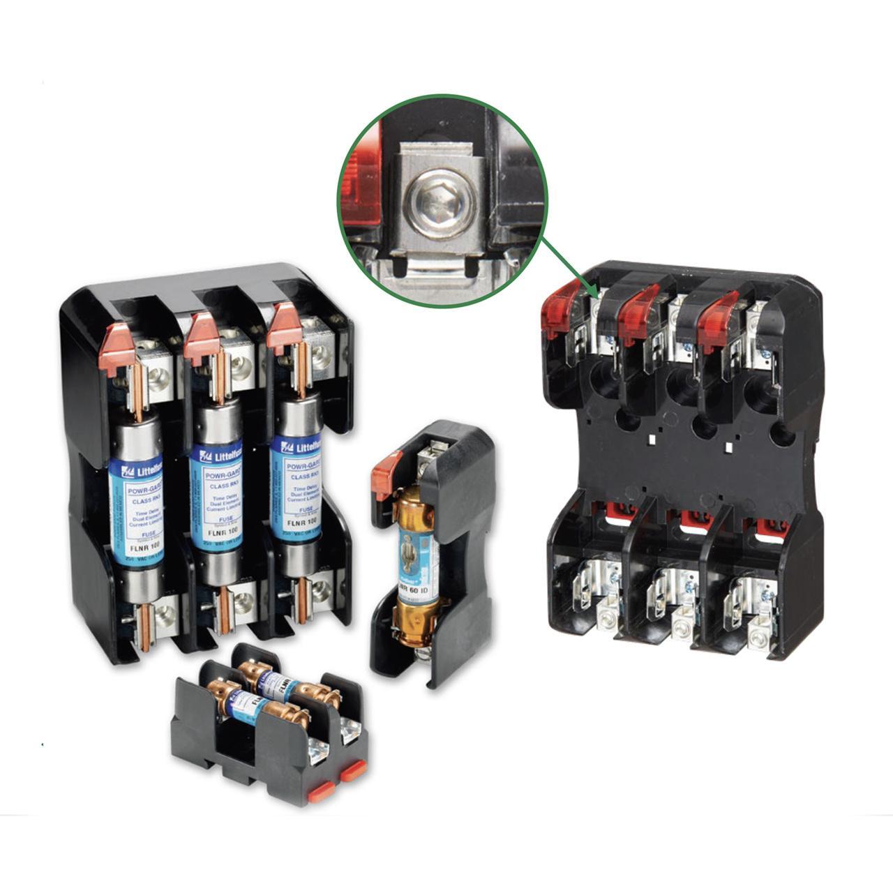
Littelfuse® POWR-GARD® LFR25030-1C Fuse Block, 250 V AC, 30 A, Class: R, 14 to 6 AWG Wire, 1 Poles

The new Littelfuse® class H and R blocks offer many advantages over previous generations that are noted in the features and benefits section. Class H and class R fuse blocks are dimensionally the same, but class R blocks incorporate A rejection feature, which only allows class R fuses to be inserted.
-
BrandLittelfuse®
-
UPC079458181265
-
Manufacturer Part NumberLFR25030-1C
-
CountryUSA|Canada
-
Temperature Rating125 deg C
-
MaterialThermoplastic
-
ClassR
-
Fuse Diameter0.563 in
-
Fuse Length2 in
-
Connection TypeBox Lug
-
Mounting TypeDIN Rail
-
Voltage Rating250 V AC
-
Amperage Rating30 A
-
SeriesLFR
-
Wire Size14 to 6 AWG
-
Number of Poles1
-
Dimensions3.15 in L x 1.13 in W x 1.58 in H
-
Suitable For Use WithFLNR/FLNR_ID, KLNR and LLNRK Series Fuse
- Universal mounting holes for easy replacement
- Only 1-hand is required to release from DIN rail (lock open lock closed)
- Reinforced fuse clips are standard on all class H and class R fuse blocks
- <0.6 mA at 600 VAC leakage current
- 200 kA rms symmetrical withstand rating
- Clip designs maximize electrical contact and minimize heat rise
- DIN rail releasable for all non-knife blade style fuses
- Lead (Pb) free
- Indication offered on most 250 and 600 VAC versions
| Competitor Name | Cross-Reference Number |
|---|---|
| Grainger | 486M97 |
-
Alternative Part Number11023032
-
UNSPSC39121629
-
IDEA Index ID11023032
-
Package DescriptionEACH
-
Standards/ApprovalsRoHS Compliant|UL Listed|CSA Certified|94 V-0 Flammability Rating|PROP65: This product can expose you to chemicals including nickel, which is known to the State of California to cause cancer.
-
Specification Sheet
-
Owners/User Manual
Recently Viewed

Littelfuse® POWR-GARD® LFR25030-1C Fuse Block, 250 V AC, 30 A, Class: R, 14 to 6 AWG Wire, 1 Poles
The new Littelfuse® class H and R blocks offer many advantages over previous generations that are noted in the features and benefits section. Class H and class R fuse blocks are dimensionally the same, but class R blocks incorporate A rejection feature, which only allows class R fuses to be inserted.
Gates® Power Transmission Plant Master® 1-1/2X200 PLANT 250 BLACK Hose, 1-1/2 in Nominal, 200 ft L, 250 psi Working, EPDM
RECOMMENDED FOR: Air and water applications requiring maximum flexibility in any industry, including mining, construction, agriculture, vehicle repair and in–plant operations. Outstanding resistance to heat and ozone. Suitable for light agricultural spraying, such as dilute solutions of herbicides.
Gardner Bender 21-101 Ring Terminal, 22 to 16 AWG Conductor, Insulated Barrel, Vinyl, Red
The Gardner Bender™ quick and always reliable crimp-type wire terminals feature color-coded barrels denoting industry standard wire gauge sizes. Available in ring, spade, disconnect and bullet styles. Vinyl insulated barrels provide a high degree of protection and carry a maximum 600 V rating. Temperature ratings for the complete line are 75 deg C (167 deg F). You will find various terminals for various circuit protection devices, all insulated to last for those any environments. Gardner Bender terminals are leading the industry in quality and durability.

8-1/2" X 4-3/4" CELLULOSE SPONGE-JWH600059 >
Penn-Union™ ST-7A-BG Ring Terminal, 22 to 18 AWG Conductor, Butted Seam Barrel, Red
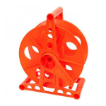
The Cord Storage Reel is designed to hold up to 150 feet of 16/3 extension cord. The side mounted handle makes it simple to wind up your cord and the wide stable base means the Cord Storage Reel will stay in place without falling down on the job. The convenient carry handle makes the Cord Storage Reel exactly that...convenient to carry to and from the job site. Made from shatter and temperature resistant thermoplastic, the Cord Storage Reel will hold up to the elements year after year.

